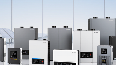
Picking out a Dual Solar Charge Controller isn't just about the specs; you really need to understand what your system is actually doing day-to-day. These controllers can serve different setups—like managing two battery banks, handling two solar inputs, or working with one big array that has separate charging outputs. And let’s be clear: those designs aren’t interchangeable. As solar expert Sean White puts it, “A charge controller is basically the traffic cop between your solar panels and your batteries.” That image is simple but so important. It needs to regulate power safely, stop overcharging, and push energy where it’s needed most.
When you're choosing one, start by considering the type of batteries you’re using. Lithium iron phosphate batteries, for example, require different charging settings than traditional lead-acid ones. Make sure to check the controller’s max photovoltaic voltage and current ratings, then compare those to your panels’ coldest voltage and the brightest sunlight you expect. Sometimes a controller seems perfect just based on specs, but in real life, it might overheat if it’s tucked away in a poorly ventilated cabinet. Little details really add up—measure twice, cut once, right?
In this guide, I’ll walk you through MPPT vs. PWM designs, independent charging channels, shared-ground limitations, temperature compensation, remote monitoring options, and low-voltage shutdown features. I'll also compare some specs from trusted names like Victron Energy, Morningstar, and Renogy. Sure, their features might look similar at first, but the way they’re wired and the software settings can vary quite a bit. So, don’t skip reading the manual—trust me on that one.
There’s no one-size-fits-all perfect controller. What works for a boat, a cabin, or a backup system depends on your specific loads, weather conditions, and how you handle maintenance. I’ve seen setups go wrong simply because the second battery bank was treated like an afterthought—that’s a mistake you want to avoid. The best Dual Solar Charge Controller will match your batteries, solar array, cable size, case, and daily energy needs. And it should have some room for future upgrades, too. Honestly, perfect planning doesn’t happen very often, but doing your homework and double-checking everything before you buy is always a good move.
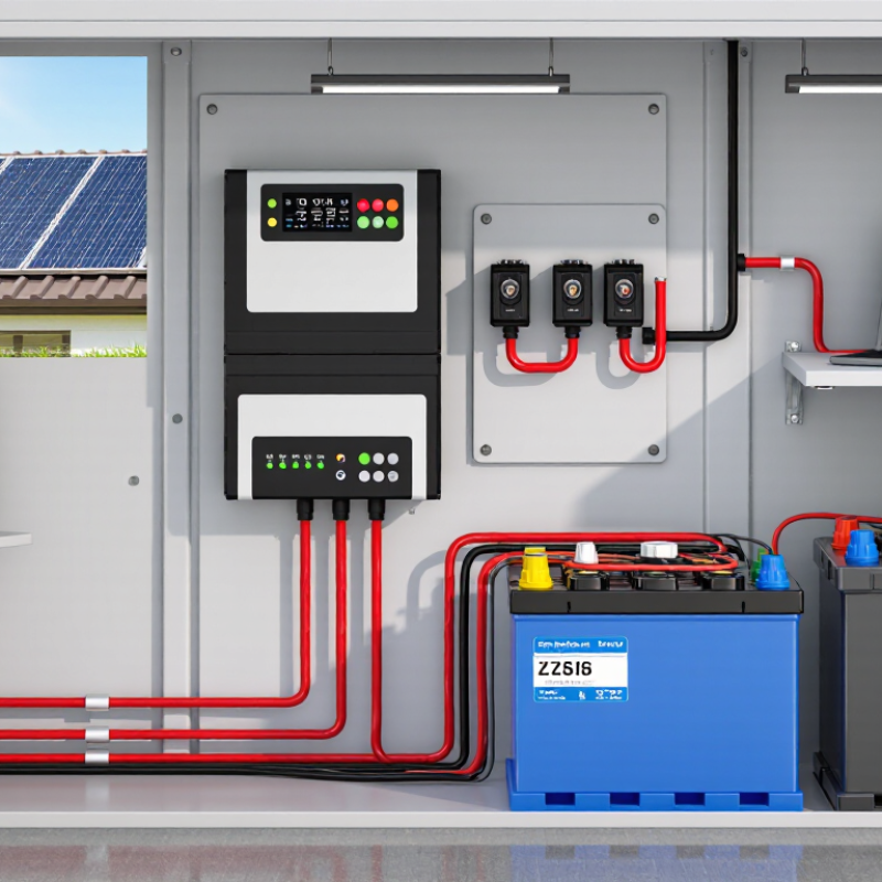
Choosing a Dual Bank Solar Charge Controller starts with your battery plan, not the panel wattage. Define whether both batteries share the same voltage, chemistry, and charging schedule. A 12 V starter battery and a 12 V house battery may need separate charging limits.
For a 24 V system, confirm that the battery bank is genuinely configured for 24 V. Two 12 V batteries in series require balanced charging and compatible protection settings. Parallel batteries need matching capacity, age, and cable length. Small differences can create uneven current flow. Measure voltage at rest and under load. Do not rely only on labels.
A Dual Bank Solar Charge Controller should provide independent outputs or clearly documented priority control. Check its rated solar input, charging current, and battery isolation method. Some controllers charge the primary battery first, then send surplus power elsewhere. That may suit a vehicle, but not two storage banks with heavy daily use. A practical test is simple: connect a multimeter, cover part of the panel, and observe each battery’s charging response. I once overlooked cable resistance during a workshop check. The controller appeared correct, but the distant battery charged slowly. That mistake remains worth remembering. Shorter cables help. Correct fuses matter. So does verifying 12 V or 24 V settings before connection.
Choosing a dual solar charge controller starts with conversion efficiency. PWM controllers usually deliver about 70–80% of the panel’s available energy, while MPPT units commonly reach 95–98% under suitable conditions. These figures align with ranges reported in off-grid system guidance from the World Bank’s ESMAP program and technical testing literature. The difference becomes visible on cold mornings, when panel voltage rises above battery voltage. MPPT can convert that extra voltage into useful charging current. PWM usually loses it as heat or unused potential.
Real installations are messier. According to the International Renewable Energy Agency’s renewable-power cost reports, system performance depends heavily on temperature, wiring, maintenance, and site conditions. A dual controller should therefore be matched to battery voltage, panel voltage, current rating, and charging profile. Check the controller’s measured efficiency curve, not only its headline percentage. A claimed 98% may apply near a specific voltage and load.
Small panels and warm climates may make PWM financially reasonable. Larger arrays, long cable runs, partial shading, or cold climates usually strengthen the case for MPPT. In field work, I have seen incorrect cable sizing erase much of the expected gain. That detail is easy to miss. Efficiency also drops when connectors corrode or batteries remain nearly full. Use independent test data where possible, and leave reasonable headroom above the array’s maximum current.
How to Choose a Dual Solar Charge Controller?
A Dual Mppt Solar Charge Controller can manage two solar inputs independently. This helps when panels face different directions or receive unequal shade. Start by checking the solar array’s rated output current. Add the two array currents together, then multiply the total by 1.25. This 125% factor provides working headroom during bright, cool conditions, when panels may briefly exceed their label ratings.
For example, two arrays rated at 12 amps each produce 24 amps combined. Multiply 24 by 1.25, giving 30 amps. Choose a controller rated for at least 30 amps, not 25 amps. Round upward when the available size is limited. Also verify the controller’s maximum solar voltage, battery voltage, and separate MPPT input limits. A controller can meet the current requirement yet fail if the panel string voltage is too high. Measure carefully. Labels can be optimistic.
Tips: Check the wiring, fuses, and battery charging limits as one system. A 40-amp controller may be suitable, but only if the battery accepts that charge rate. Leave extra room for future panels when practical. However, oversizing without checking voltage wastes money and may create confusion during installation. Field conditions differ from test ratings, so record actual midday current after commissioning. I have found that one early measurement often reveals a misplaced assumption.
| Example | Battery System Voltage | Total Solar Array Rating | Array per Controller | Estimated Charge Current (Array ÷ Battery Voltage) |
125% Design Current (Total) |
Minimum Design Current (Each Controller) |
Practical Dual-Controller Selection |
|---|---|---|---|---|---|---|---|
| 1 | 12 V | 400 W | 200 W | 33.3 A | 41.7 A | 20.9 A | 2 × 30 A |
| 2 | 12 V | 600 W | 300 W | 50.0 A | 62.5 A | 31.3 A | 2 × 40 A |
| 3 | 12 V | 800 W | 400 W | 66.7 A | 83.3 A | 41.7 A | 2 × 50 A |
| 4 | 24 V | 1,200 W | 600 W | 50.0 A | 62.5 A | 31.3 A | 2 × 40 A |
| 5 | 24 V | 1,600 W | 800 W | 66.7 A | 83.3 A | 41.7 A | 2 × 50 A |
| 6 | 48 V | 2,400 W | 1,200 W | 50.0 A | 62.5 A | 31.3 A | 2 × 40 A |
| 7 | 48 V | 3,840 W | 1,920 W | 80.0 A | 100.0 A | 50.0 A | 2 × 60 A |
| Calculation basis: Required total controller current = 1.25 × solar array rated power ÷ nominal battery voltage. The examples assume the array is divided evenly between two controllers. Select the next available controller rating above the calculated current, and verify the controller’s maximum photovoltaic input voltage, maximum PV power, battery compatibility, conductor ampacity, overcurrent protection, and installation requirements before purchase. | |||||||
When choosing a Dual Input Solar Charge Controller, start with the panels’ open-circuit voltage, or Voc. This is the voltage present before a load draws power. Add the Voc values when panels are wired in series. Then compare the total with the controller’s maximum PV voltage. Never match them too closely. Cold weather can raise panel Voc above its label value. Use the lowest expected site temperature and the panel’s temperature coefficient.
For example, two 45 V panels may produce 90 V in mild conditions. On a cold morning, their combined Voc can rise several volts. A controller rated for 100 V may then have too little safety margin. I would select a lower string voltage or a controller with a higher verified limit. Check the datasheet, not only the product box. Small wording differences matter, especially between maximum PV voltage and maximum operating voltage. They are not interchangeable.
A dual-input design also needs separate checks. Confirm whether each input has its own voltage limit, tracking range, and wiring requirements. Do not assume both inputs share the same protection. Record the panel Voc, temperature coefficient, series count, and cable route before installation. Recheck the calculation for winter conditions. This step feels repetitive. It prevents expensive errors. One detail is easy to miss: voltage can rise while the battery is nearly full and charging current falls.
How to Choose a Dual Solar Charge Controller?
A dual-battery system needs more than two output terminals. IEA PVPS reported that global solar capacity exceeded 1.6 terawatts by the end of 2023. More installations now serve vehicles, cabins, and backup loads. A mismatched controller can waste that energy or shorten battery life.
Check the battery chemistry first. Flooded and AGM lead-acid batteries usually require bulk, absorption, and float stages. Lithium iron phosphate batteries need controlled constant-current and constant-voltage charging. They generally should not receive continuous float charging. Charging below 0°C can cause lithium plating, so a battery-management system or low-temperature cutoff matters. It is easy to overlook this detail.
Temperature compensation is equally important. Lead-acid charging voltage typically changes about 3–5 millivolts per cell for each Celsius degree. On a 12-volt battery, that equals roughly 18–30 millivolts per degree. Place the sensor on the battery case, not beside the controller. For lithium batteries, automatic lead-acid compensation may be harmful. Disable it unless the battery documentation allows it. An Mppt Dual Battery Solar Charge Controller can improve energy harvest during cool, weak sunlight, but MPPT cannot correct incorrect charging limits. I have seen systems sized correctly still underperform because the second battery used a different chemistry. Recheck both charging profiles. Temperature readings also deserve skepticism when the sensor hangs loose in warm air.
Compare battery chemistry, charging-stage voltage, and temperature compensation before selecting a dual solar charge controller. Values shown are representative settings for a 12 V battery system.
Lead-acid batteries generally require absorption and float charging, with temperature compensation of approximately −24 mV/°C per 12 V battery. LiFePO4 batteries typically use a controlled absorption stage, require little or no temperature compensation, and usually do not need continuous float charging. Confirm the final setpoints with the battery manufacturer's specifications.
Choosing a dual solar charge controller requires more than comparing charging current. The controller should share loads predictably between two battery banks or solar inputs. Check whether it supports balanced charging, priority charging, or independent channels. A clear current display helps confirm real performance during cloudy mornings and heavy afternoon demand. Uneven sharing can overwork one channel and shorten battery life.
Protection ratings deserve close attention. Look for overcurrent, reverse-polarity, overtemperature, short-circuit, and surge protection. In outdoor installations, an IP65 or higher enclosure keeps dust out and resists water jets. It is not designed for immersion. Mount the unit under a sheltered panel, use sealed cable glands, and leave space for airflow. Condensation remains a practical risk, even with a strong enclosure rating.
Tips: Match the controller’s total current rating with the array and expected load, not only the panel label. Use correctly sized fuses near each battery connection. Inspect terminal heating after the first week. I have seen a well-rated controller fail early because a loose cable created heat. That mistake is easy to miss. Also, verify whether the stated IP rating applies after installation, since poorly fitted glands can weaken protection. When load conditions change, record both channel currents instead of trusting the display alone. A small imbalance may be acceptable, but unexplained changes deserve investigation.
Small wind power is gaining attention as a practical complement to solar and other distributed renewable systems. International renewable-energy and wind-industry reports highlight continued interest in decentralized generation, especially for farms, remote facilities, hybrid microgrids, and locations with suitable local wind resources. In this market, efficient energy capture, reliable battery charging, and clear system feedback are essential for making small wind installations easier to operate and maintain.
The 3 kW MPPT wind controller is designed for these requirements. Its advanced MPPT algorithm continuously tracks the turbine’s maximum power point, helping maintain efficient energy conversion as wind speed changes. A high-performance ARM processor supports fast calculations and stable long-term operation, while the built-in boost converter improves DC voltage conversion efficiency. The controller monitors input voltage and current, power output, battery voltage, charging and discharging current, turbine speed, MPPT status, DC output conditions, and braking status. Automatic identification supports standard 12V, 24V, and 48V battery systems, with manual settings available for customized battery packs. An integrated braking resistor provides active protection during high winds or battery full-charge conditions, while the 2.0-inch IPS TFT LCD enables convenient onsite viewing and configuration.
PWM controllers commonly deliver 70–80% of available panel energy. MPPT controllers often reach 95–98% under suitable conditions. Actual results vary with temperature, wiring, shading, and battery condition. Headline ratings can mislead.
MPPT usually helps with larger arrays, long cable runs, partial shading, and cold climates. Cold panels can produce higher voltage than the battery needs. MPPT converts more of that voltage into charging current. PWM may lose it as heat.
Yes, especially with small panels and warm climates. It may cost less and work adequately in simple systems. The expected energy gain from MPPT may be modest. Do the math first.
Record each panel’s open-circuit voltage, or Voc. Add Voc values when panels are connected in series. Keep the cold-weather total below the controller’s maximum PV voltage. Do not match the limits closely.
Panel Voc rises as temperature falls. Two 45-volt panels may exceed 90 volts on a cold morning. A 100-volt controller could have too little safety margin. Check the temperature coefficient.
Confirm each input’s voltage limit, tracking range, and wiring requirements. Do not assume both inputs share identical protection. Record series counts, cable routes, and expected winter temperatures. Recheck everything.
Flooded and AGM batteries generally use bulk, absorption, and float stages. Lithium iron phosphate batteries require controlled constant-current and constant-voltage charging. They usually should not receive continuous float charging. A suitable battery-management system remains important.
Lead-acid charging voltage changes with battery temperature. A 12-volt battery may need roughly 18–30 millivolts of adjustment per Celsius degree. Place the sensor firmly on the battery case. Loose sensors can report warm air instead.
No. MPPT improves energy harvesting, but it cannot correct wrong charging limits. Different battery chemistries may need different profiles. Lithium batteries can suffer damage from charging below 0°C. That detail is easy to miss.
Undersized cables, corroded connectors, shading, and poor maintenance reduce performance. Charging efficiency also falls when batteries are nearly full. Leave reasonable current headroom above the array’s maximum output. I might still underestimate wiring losses.
Choosing the right Dual Solar Charge Controller begins with understanding your battery setup and energy demands. Confirm whether the system uses 12 V or 24 V batteries, and determine whether both batteries require independent charging or balanced load sharing. When comparing technologies, PWM controllers are generally more affordable but may deliver only about 70–80% efficiency, while MPPT models can reach approximately 95–98% by optimizing available solar power. For safe sizing, select a controller rated at least 125% of the solar array’s maximum output current.
Also verify that the solar panel open-circuit voltage remains below the controller’s maximum PV voltage, especially in cold conditions. Check compatibility with the battery chemistry, required charging stages, and temperature-compensation features to support reliable, efficient charging. Finally, review load-sharing functions, overcurrent and overvoltage protection, ventilation, and enclosure durability. An IP65 or higher rating can provide better protection against dust and water, making the controller more suitable for demanding outdoor installations.